Learning Center

Fire Alarm Training Curriculum

A guided NFPA 72 learning path from fundamentals to advanced systems, in original plain language. These are learning aids only — always verify exact requirements in the officially adopted standards and with your AHJ.

NFPA 72 Learning Path

0/9 core modules passed

Ask a Fire-Code Question

Plain-language answers to NFPA 72/70 questions, grounded in cited web sources. Educational guidance only — not code or design authority.

Basics of Fire Alarm Systems

A fire alarm system detects fire conditions, alerts building occupants, and can notify responders. It combines a control panel, initiating devices, notification appliances, power sources, and interconnecting pathways working as one coordinated system.

Why it matters

Understanding how the parts work together helps you place devices logically, read a sequence of operation, and communicate clearly with designers, installers, and inspectors.

Introduction to Fire Alarm Systems

A plain-language overview of how the fire alarm control panel (FACP), initiating devices and notification appliances work together in a building.

Watch on YouTube
Learning objectives
  • Identify the core components of a fire alarm system — initiating devices, control unit (FACP), notification appliances, and power supplies.
  • Distinguish conventional, addressable, and hybrid system types.
  • Trace a signal from detection through the panel to notification, and explain why secondary (battery) power matters.

The five building blocks

Every system generally has a control panel (the brain), initiating devices (inputs such as detectors and pull stations), notification appliances (outputs such as horns and strobes), a power supply with battery backup, and pathways (the wiring or wireless links that connect everything).

Conventional vs. addressable

Conventional systems group devices into zones, so the panel knows the zone but not the exact device. Addressable systems give each device a unique address, so the panel can pinpoint the specific device that activated. Many buildings use a hybrid of both.

How a signal flows

An initiating device senses a condition and reports to the panel. The panel evaluates it against its programmed sequence of operation, then activates outputs — sounding alarms, sending a signal to a monitoring service, and often triggering functions like door release or elevator recall.

Interactive walkthrough

Step 1 of 3

The five building blocks

Every system generally has a control panel (the brain), initiating devices (inputs such as detectors and pull stations), notification appliances (outputs such as horns and strobes), a power supply with battery backup, and pathways (the wiring or wireless links that connect everything).

Key terms
FACP
Fire Alarm Control Panel — the central unit that monitors inputs and drives outputs.
Initiating device
An input that reports a condition (smoke, heat, manual pull, waterflow).
Notification appliance
An output that warns occupants (horn, strobe, speaker).
Sequence of operation
The programmed logic describing what the system does when a given input activates.
Common pitfalls / potential review items
  • • Confusing detection (inputs) with notification (outputs).
  • • Assuming one panel layout fits every building.
  • • Forgetting that power and battery backup are part of the system.
Guided practice

Which component is the 'brain' that monitors circuits and initiates the alarm response?

Independent challenge

A device that DETECTS a fire condition and reports it to the panel is called a(n):

Code sections every tech should know

References use NFPA 72 2019/2022 numbering — section numbers can shift between editions, so confirm in the edition your AHJ has adopted.

Code section 1

Circuit classes describe how a pathway survives a fault

Circuit classes describe how a pathway survives a fault

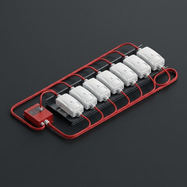
Chapter 12 names every circuit by how it behaves when something goes wrong. Class B is the everyday circuit: one open or ground fault is reported as a trouble, and devices past the break stop working. Class A loops back to the panel, so a single open still leaves every device operating while the trouble is reported. Class X adds isolation so a short circuit is also survived. Class N covers network (Ethernet-style) pathways. The designer picks the class; the installer has to wire it so the panel can actually tell the difference.

NFPA 72 reference

Chapter 12 — Circuits and Pathways

12.3 Pathway Class Designations (12.3.1 Class A, 12.3.2 Class B, 12.3.5 Class N, 12.3.6 Class X)

On the job

A hospital spec calls for Class A on the SLC. The installer lands the return conductors on the same terminals as the outgoing pair to save time. Everything works on the acceptance test — until a single open is simulated and half the loop drops out. The loop was wired Class B with extra copper; the return had to be moved to the panel's dedicated Class A terminals.

Quick check

1. On a Class B circuit, a single open conductor results in:

2. What distinguishes Class A from Class B?

3. Class X adds the ability to survive:
Code section 2

Every circuit has to prove it's still intact

Every circuit has to prove it's still intact

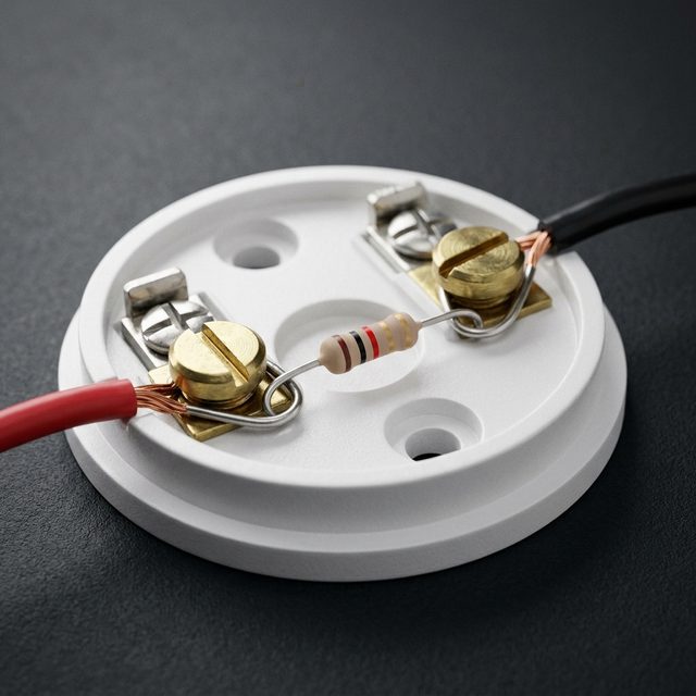
Initiating device circuits, signaling line circuits, and notification appliance circuits must be monitored for integrity: a single open or a single ground fault anywhere on the pathway must be reported as a trouble within 200 seconds. That is why Class B circuits end in an end-of-line device and why a single device wired with a T-tap can silently defeat supervision — the panel still sees the end-of-line resistor even though the branch is cut off. The requirement also covers the power connections to remote power supplies and the connections to notification appliances.

NFPA 72 reference

Chapter 12 — Circuits and Pathways

12.6 Monitoring Integrity (12.6.1 installation conductors, 12.6.2 trouble indication within 200 s)

On the job

A tech adds a horn/strobe for a new office by T-tapping the NAC in a junction box. The panel shows normal because the end-of-line resistor is still on the original run. Months later the new wire is cut by a drywall screw — no trouble, no strobe, and nobody knows until the annual test. Re-routing the NAC in and out of the new appliance restores supervision.

Quick check

1. A single open on a monitored circuit must be annunciated as a trouble within:

2. Why is a T-tap on a Class B circuit a code problem?

Code section 3

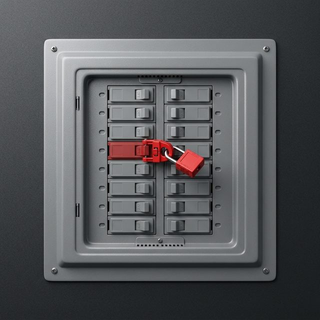
The panel gets its own breaker — and it's marked

The panel gets its own breaker — and it's marked

Primary power for a fire alarm control unit comes from a dedicated branch circuit. No other loads share it, the circuit disconnecting means (the breaker) must have a red marking, be accessible only to authorized personnel, and be identified as FIRE ALARM CIRCUIT. The location of that breaker is recorded at the control unit so a technician — or the fire department — can find it. A mechanical lock-on device is commonly used so the breaker can't be casually switched off.

NFPA 72 reference

Chapter 10 — Fundamentals

10.6.5 Primary Power Supply; 10.6.5.2 dedicated branch circuit, marking, and accessibility (10.6.5.2.1 through 10.6.5.2.3)

On the job

A panel keeps going to battery every night. The installer finds it shares a breaker with the parking-lot lighting contactor, which trips on a photocell fault. Moving the panel to its own breaker, painting the handle red, adding the lock-on clip and labeling it FIRE ALARM CIRCUIT fixes the nuisance — and the code violation.

Quick check

1. The branch circuit feeding a fire alarm control unit must be:

2. The fire alarm breaker must be:

Code section 4

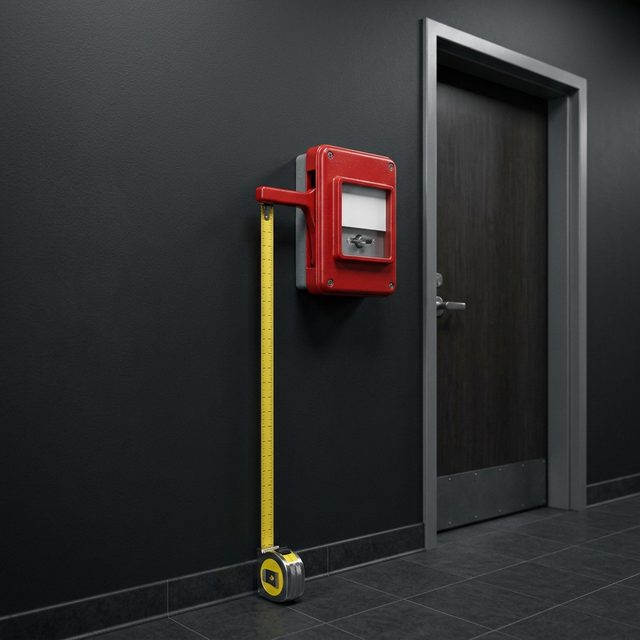
Where a pull station goes is in the code, not up to you

Where a pull station goes is in the code, not up to you

Manual fire alarm boxes are mounted so the operable part is between 42 and 48 inches above the finished floor. They go within 5 feet of each exit doorway on every floor, and additional boxes are added so the travel distance to the nearest box never exceeds 200 feet. They must be unobstructed, accessible, and conspicuous — a pull station behind a door swing or hidden by a display rack is a deficiency even if it works perfectly.

NFPA 72 reference

Chapter 17 — Initiating Devices

17.15 Manually Actuated Alarm-Initiating Devices (mounting height 17.15.5, location near exits 17.15.8, 200 ft travel distance 17.15.9; numbered 17.14 in the 2016 edition)

On the job

A retail tenant installs new shelving and the pull station by the rear exit ends up behind a gondola display. The device is in perfect working order, but the AHJ writes it up: it is no longer conspicuous or accessible. The fix is moving the shelving — or relocating the station within 5 feet of the exit where it can be seen.

Quick check

1. A pull station's operable part must be mounted at:

2. Maximum travel distance to the nearest manual fire alarm box is:

3. Manual boxes are required within what distance of each exit doorway?

Code section 5

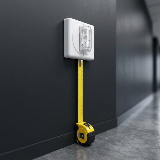
Wall strobes live between 80 and 96 inches

Wall strobes live between 80 and 96 inches

Wall-mounted visible notification appliances (strobes) are installed so the entire lens is not less than 80 inches and not more than 96 inches above the finished floor — or, where the ceiling is lower, within 6 inches of the ceiling. The candela rating is chosen from the room-spacing tables in Chapter 18 based on room size and mounting position; a strobe that is too low, too high, or too dim does not provide the coverage the tables assume, even if it flashes.

NFPA 72 reference

Chapter 18 — Notification Appliances

18.5.5 Appliance Location (18.5.5.1 wall-mounted visible appliances 80-96 in.); 18.5.5.4 room spacing tables

On the job

A contractor mounts corridor strobes at 7 ft (84 in.) to the bottom of the device — but these are combination horn/strobes where the lens sits 4 in. below the top, putting the lens bottom at about 78 in. The AHJ measures the lens, not the box. Each appliance is raised so the full lens falls in the 80-96 in. band.

Quick check

1. The lens of a wall-mounted strobe must sit:

2. Strobe candela ratings are selected from:

Code section 6

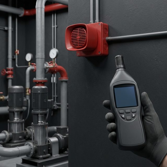
Alarm sound has to beat the room's noise, not just exist

Alarm sound has to beat the room's noise, not just exist

In public mode, audible notification must be at least 15 dBA above the average ambient sound level, or 5 dBA above the maximum sound level lasting 60 seconds or more — whichever is greater — measured 5 feet above the floor. Sleeping areas need at least 75 dBA at the pillow, and the alarm must be the Temporal-3 pattern for evacuation. A horn that is "loud" in the hallway may still fail in a mechanical room or a noisy production floor, so the design is checked with a sound meter, not an ear.

NFPA 72 reference

Chapter 18 — Notification Appliances

18.4.4 Public Mode Audible Requirements (18.4.4.1); 18.4.5 Sleeping Area Requirements (75 dBA); 18.4.2 Temporal-3 evacuation signal

On the job

During acceptance testing of a machine shop the meter reads 92 dBA ambient with the presses running. The single horn in the shop produces 95 dBA — only 3 dB over. The fix is adding appliances (or a strobe-only design where the AHJ allows it) until the alarm measures at least 107 dBA at 5 ft, or the space is treated as a visible-notification area.

Quick check

1. Public mode audible signals must be at least how much above average ambient?

2. Minimum sound level at the pillow in a sleeping area is:

3. Audible levels are measured at:

Related modules

We never embed copyrighted code text — add your own authorized references.

Knowledge Check

1. An addressable system differs from a conventional one because it:

2. A horn/strobe is best classified as a(n):

3. The basic signal flow of a fire alarm system is:

4. Secondary (battery) power exists primarily to:

5. Battery backup exists primarily to:

Troubleshooting tie-in

Practice an IDC open-circuit trouble in the Lab

Summary

Key takeaways

  • Identify the core components of a fire alarm system — initiating devices, control unit (FACP), notification appliances, and power supplies.
  • Distinguish conventional, addressable, and hybrid system types.
  • Trace a signal from detection through the panel to notification, and explain why secondary (battery) power matters.

Additional Resources

Code References

Adopted Code Editions — Verify Locally

Always confirm the NFPA 72 and NFPA 70 (NEC) editions adopted by your jurisdiction before using any concept from this trainer.

Best Practices

Working With Your AHJ

Engage the Authority Having Jurisdiction early. Local amendments and interpretations govern the final design.

Fire Alarm Blueprint Trainer provides educational guidance only. It does not replace professional engineering, licensed electrical work, approved fire alarm design, manufacturer installation instructions, applicable codes, or AHJ review.

© 2026 Fire Alarm Blueprint Trainer · Educational tool · Not affiliated with NFPA.